
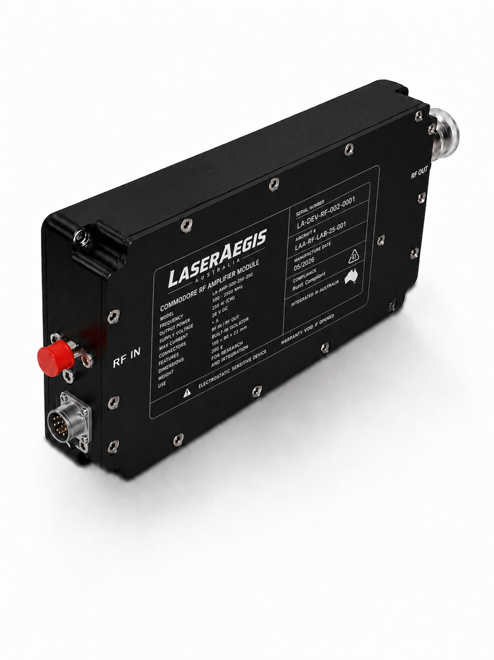
An RF power amplifier can meet its frequency and output-power requirements and still be operating at the wrong point for the job.
A continuous-wave test requiring low distortion places different demands on an amplifier from a pulsed experiment with a constrained thermal envelope. Adjustable bias gives engineers another way to manage that trade-off, provided the selected operating points are controlled and verified.
When a fixed bias becomes a constraint
A fixed operating point is often the right choice when the waveform and operating conditions are stable. Configuration adds little value if the amplifier will always perform the same task.
The constraint appears when one RF platform must support different test conditions. A research system may require low-distortion operation for one activity, then place more emphasis on efficiency for another. An EMC susceptibility test may involve different levels, modulation conditions and dwell periods.
A higher quiescent-current setting may support the required linearity but add unnecessary DC power and cooling demand during other work. A lower-current setting can reduce idle dissipation, with different gain and distortion behaviour. Choosing between them requires the waveform, output level and thermal limits to be considered together.
What changes between Class A and Class AB?
The operating class of an RF power stage relates to its transistor bias and conduction behaviour. Drive level, device technology, matching networks, load line, frequency, temperature and output back-off also affect the measured result.
Biasing toward Class A generally increases quiescent current. Under suitable conditions, this can improve linearity, but it also increases idle dissipation and cooling demand. Biasing toward Class AB reduces quiescent current and can offer a useful efficiency–linearity compromise.
| Consideration | Toward Class A | Toward Class AB |
|---|---|---|
| Quiescent current | Generally higher | Generally lower |
| Idle heat | Greater cooling demand | Lower idle dissipation |
| RF performance | May support lower distortion | May improve efficiency |
| What to verify | Gain, output power, distortion and temperature under the intended conditions | |
These are engineering tendencies, not measured Commodore AB performance. The class label alone does not determine the RF result.
Pulsed operation needs particular care. A lower duty cycle may reduce average dissipation, but peak electrical stress, pulse width, repetition frequency and transient thermal behaviour still matter. If the amplifier remains biased between pulses, quiescent dissipation continues during the off-time.
The Commodore AB configurable-bias concept
LaserAegis is developing Commodore AB around adjustable RF power-stage bias. Depending on the amplifier configuration, the operating point may be set manually or through a digitally controlled implementation.
For software-enabled configurations, the intended architecture supports Ethernet-based supervisory control and monitoring. The interface, operating profiles and adjustment range depend on the amplifier design and customer requirements.
A controlled operating profile brings together:
- Power-stage bias and amplifier enable sequencing.
- Permitted RF drive and output range.
- Current, temperature and monitoring limits.
- Local fault responses and the RF performance verified for that state.
Changing the operating point with RF present requires a validated transition sequence, including settling time and any input muting. This is a configuration-specific engineering decision.
Supervisory control and local protection
Ethernet connects an amplifier to a wider test system. Local protection gives the RF stage a defined response when conditions exceed its limits, including when the supervisory connection is unavailable.
Depending on the selected hardware, the intended Commodore AB architecture can monitor RF output power, supply voltage and current, temperature, enable state, protection status and operating configuration.
Overtemperature, overcurrent and other configured protection responses are intended to operate locally. Sensors, thresholds, latched states, power-up defaults and recovery sequences need to be defined and tested for each configuration.
Frequency and power depend on the configuration
The target Commodore AB family envelope spans approximately 80 MHz to 6 GHz and 22 W to 1 kW across customer-specific configurations. A single unit does not cover that entire range, and every power level is not available at every frequency.
Each amplifier would be designed for a specified band and output level. Achievable performance depends on instantaneous bandwidth, waveform, CW or pulsed operation, linearity targets, device technology, power combining, available DC power and cooling.
GaN and LDMOS are evaluated against these requirements. The semiconductor choice is made for the individual design, alongside its mechanical, monitoring and protection requirements.
Where adjustable bias can add value
RF test, EMC susceptibility testing and research platforms can benefit when operating requirements change between activities. Defence-related use cases include laboratory and system-level RF development supporting communications, radar, electronic-warfare and counter-UAS programmes.
Consider a laboratory that uses the same RF chain for a linearity-sensitive measurement and a pulsed experiment. Separate bias profiles may be useful if each provides a measured advantage and stays within the amplifier’s electrical and thermal limits. This is an illustrative use case, not a reported Commodore AB test result.
Recording the selected profile with the test result makes the operating state traceable. A fixed bias remains a sensible choice when it already meets every required condition.
What needs to be verified
Representative configurations need measurement under defined conditions. The verification plan should include the metrics relevant to the application:
- Output power, gain, and quiescent and driven supply current.
- Drain efficiency or power-added efficiency.
- Harmonics, intermodulation, or waveform-specific ACPR and EVM.
- Baseplate temperature and transient thermal behaviour.
- Bias-transition settling, local protection and communication-loss response.
For a meaningful comparison, record frequency, waveform, drive level, output power, supply and cooling conditions. Those results define which profile is appropriate for each task.
Starting with your RF requirements
A useful starting brief includes the required band, output power, waveform and duty cycle. If known, add gain and linearity targets, DC supply, cooling, mechanical envelope, control interfaces, expected quantity and verification requirements.
LaserAegis can use that brief to assess whether a fixed operating point meets the application, or whether a small number of verified bias profiles would add practical value.
Put your requirements in context
What does your RF
application need?
Start with your band, power and waveform. We’ll help assess the operating-point and integration requirements.
Discuss Your RF Amplifier Requirements Or email xander@laseraegis.devTechnical reference
For the general relationship between bias current and RF performance: Analog Devices — Meeting Biasing Requirements of Externally Biased RF/Microwave Amplifiers. This reference does not validate Commodore AB product performance.