
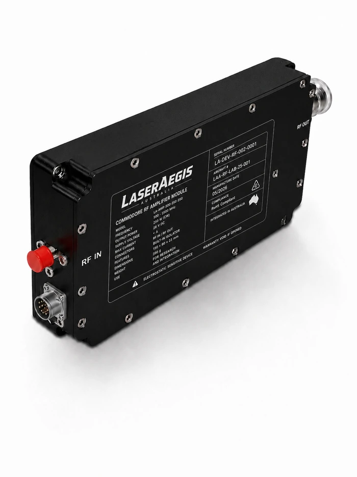
A request for a custom RF amplifier can describe several different problems. The required linear output power may exceed what an available module can deliver. The RF performance may be suitable, but the module cannot reject heat into the proposed installation. Or the customer may need a complete rack assembly, with power supplies, filtering and remote control, around an otherwise standard amplifier.
Each problem calls for a different engineering response. Replacing the RF design will not resolve an inadequate cooling interface. Adding a controller will not recover output power lost to compression.
The useful starting point is to identify the requirement that the available hardware cannot meet. That establishes what can be retained, what needs to change and how the resulting solution will be verified.
Establish the performance gap
“100 W output” is incomplete without its operating conditions. It could mean saturated CW power, peak pulse power or average output while meeting a specified distortion limit. Those requirements can lead to different amplifier choices.
For a modulated signal, the available linear output depends on the waveform and acceptable distortion. Operating further below saturation may improve linearity, but it also changes efficiency and the power available to the application. A larger nominal rating is therefore useful only if the amplifier meets the required performance at the intended operating point.
The same care applies to pulsed operation. Duty cycle alone does not define the thermal requirement: pulse duration and repetition rate also affect the temperature reached within the device. Two operating sequences with the same average duty cycle can require different thermal assessments.
Before choosing a product or proposing changes, establish:
- the frequency band and required performance across it;
- output power, its measurement point and the applicable linearity limit;
- waveform, pulse timing and longest operating sequence;
- available input drive and DC supply conditions;
- expected load mismatch;
- cooling conditions at the amplifier interface.
These inputs provide a basis for comparing measured or specified performance. Any missing information should remain an explicit assumption until it can be resolved.
Locate the change in the system
Once the gap is understood, the engineering team can decide where to address it.
Consider an illustrative requirement for 100 W at a subsystem output connector. If a filter and cable after the amplifier introduce 1 dB of loss, the amplifier must deliver approximately 126 W before those losses, even before adding design margin. A 100 W module cannot meet that requirement at the specified measurement point.
The next decision is whether to reduce the path loss or increase amplifier output. Increasing power may also increase supply demand and heat dissipation. Reducing loss could preserve the existing amplifier, although the alternative filter must still meet its rejection requirement.
Other gaps lead elsewhere:
| Requirement gap | Engineering response to assess | Evidence needed |
|---|---|---|
| Required distortion limit is missed at target output | Operating point, amplifier selection or RF redesign | Performance with the specified waveform and output level |
| Module exceeds its thermal limit in the installation | Mounting interface, heat spreading, cooling provision or amplifier efficiency | Thermal behaviour in the representative installation |
| Platform cannot command or monitor the amplifier | Interface electronics, controller or firmware changes | Command handling, telemetry and fault-response tests |
| Customer needs several channels in one assembly | Shared power, cooling, RF isolation and supervisory control | Behaviour with relevant channels operating together |
| Packaging cannot accommodate the module | Mechanical adaptation or alternative architecture | RF and thermal performance after integration |
The preferred solution may retain the existing RF hardware and change the surrounding assembly. It may also require a revised amplifier design. The distinction should follow the requirement and supporting evidence.
Set the scope of customisation before committing hardware
An existing design is valuable when its known performance remains relevant to the new application. Reusing it can reduce development work, but only if the modifications preserve the assumptions behind that performance.
A connector relocation deserves a review of RF routing, grounding and assembly access. A different heatsink changes the thermal boundary. A higher-power device can affect matching, bias, stability, current demand and protection. Changing restart behaviour after a fault requires agreement with the platform controller.
For a proposed adaptation, establish three things early:
- Which parts of the design and supporting evidence can be reused?
- Which changes introduce new uncertainty?
- Which analyses and tests will close that uncertainty?
If an adaptation requires substantial changes to the RF stages, supply, controls and mechanical arrangement, compare it with a new design before committing to the existing platform. Familiar hardware does not automatically mean a smaller development programme.
An unchanged commercial off-the-shelf amplifier remains a valid outcome. Where it meets the application, the remaining work may consist of confirming interfaces, defining acceptance conditions and arranging support. A good first check is whether a product in LaserAegis's RF amplifier range already fits. Custom engineering effort should be directed towards an identified gap.
Define what the customer will receive
The required delivery may be an amplifier module, a packaged unit or an integrated RF subsystem. That boundary affects both the engineering scope and the customer’s remaining work.
For a subsystem, responsibilities may extend to power conversion, filters, switching, sensing, cooling and supervisory control. These functions need agreed behaviour at their interfaces.
For example, “VSWR protection” leaves several questions open. Does a mismatch cause reduced output or a latched shutdown? What information reaches the host controller? Under what conditions can transmission resume? How will that sequence be demonstrated during acceptance?
A useful proposal should identify the delivered configuration, interface responsibilities, operating limits and verification scope. It should also identify customer-supplied items, such as a cold plate or power source, whose characteristics affect performance.
Manufacturing and test responsibilities should be equally clear. Design ownership, assembly location, production testing and specialist environmental testing are separate matters. The customer needs to understand who controls each activity and which records accompany the hardware. This allows procurement teams to compare the work included in competing offers. A module price and a subsystem price are meaningful only alongside the integration and testing that each leaves to the customer.
On LaserAegis programmes, we design the amplifier and carry out its assembly, with specialist manufacturing partners supporting where the programme requires it. RF performance and pre-compliance verification are performed in-house. Where formal EMC or environmental qualification is needed, we arrange it with qualified or accredited partner facilities, and their test reports can be included in the delivery documentation agreed for the project.
Keep the design basis available after delivery
The requirements baseline, interface definitions, approved configuration and test results remain useful throughout the product’s life.
Return to the 100 W example. With 1 dB of loss between the amplifier and the output connector, the amplifier needed to deliver about 126 W. Suppose the filter is later replaced with one that loses 1.5 dB, even though it still meets the rejection requirement. The same 100 W at the connector now needs about 141 W from the amplifier (100 × 10^(1.5/10) ≈ 141.3 W), around 12% more, again before any design margin.
That extra half a decibel reaches well beyond output power. The higher level typically means more supply current, more heat to remove and different margins against the protection thresholds. The thermal results and acceptance measurements recorded for the original configuration no longer describe the new operating point.
With the design basis to hand, the response can be defined quickly: compare the new requirement with the margin the original design held, repeat the affected measurements (output power and linearity at the new level, thermal behaviour, protection thresholds) and record the results against the revised configuration. Without it, the first task is to reconstruct what the original assumptions were.
Other changes follow the same pattern. A replacement component may require an assessment of gain, stability or thermal behaviour. A revised waveform can change the usable output or cooling requirement. Repeat orders need a defined configuration and agreed acceptance criteria. An in-service fault is easier to investigate when the delivered unit can be related to its design and test records.
Design Authority provides technical responsibility for these decisions within the agreed scope. Lifecycle support should specify how changes are assessed, when further testing is required and how maintenance or replacement needs will be handled.
The customer can then discuss a change with an engineering team that understands the basis of the supplied solution.
Working with LaserAegis Australia
LaserAegis Australia combines RF amplifier products with in-house design and architecture-level engineering. We work with customers to establish the requirement, assess available designs and define the customisation needed for the application.
That work can cover an amplifier configuration or the wider subsystem around it. Our Design Authority role connects the agreed design with integration, verification and validation, acceptance, commissioning and ongoing support. The scope of each engagement establishes the responsibilities, deliverables and lifecycle services required.
For an initial discussion, send the frequency band, required output and measurement point, waveform, duty cycle, supply, cooling conditions, mechanical constraints and control interface. Include expected quantities, delivery needs and any required test evidence.
If part of the specification is still open, identify it. We can help resolve the engineering questions and determine the appropriate amplifier solution.